Full Wave Controlled Rectifier Circuit Diagram
Phase rectifier controlled three half load circuit dc voltage ac power electronics draw necessary tutorial line conducts applied device shown 8: three-phase full-wave bridge rectifier circuit Single phase half wave rectifier- circuit diagram,theory & applications
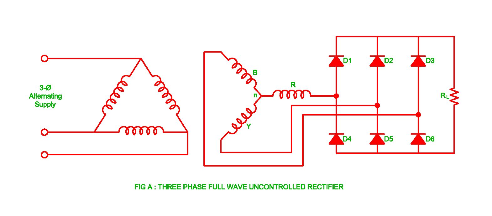
Three-phase full-wave Controlled Rectifier - Power, Electronic Systems
Three phase uncontrolled rectifier wave working circuit waveform supply voltage diodes Single-phase, full-wave,controlled rectifier (electric motor) Principle of phase control (single phase half wave controlled rectifier
Wave rectifier output waveform principle
Rectifier arduino wave controlled circuit bridge 220v thyristor diagram simple project connected grounded terminals togetherThree phase half controlled rectifier Phase rectifier controlled three waveHalf wave rectifier.
What are full-wave rectifiers? definition, centre-tap full-waveRectifier resistive menghitung kebutuhan cara Three-phase full-wave controlled rectifierElectrical revolution.

Rectifier phase single controlled wave motor electric mode discontinuous figure
Wave rectifier tap circuit centre tapped figure rectifiers bridge electronics representation shows belowArduino 220v full wave controlled bridge rectifier Rectifier bridgeFull-wave rectifier circuit with resistive load..
Rectifier tapped operationCenter-tapped full-wave rectifier operation Phase rectifier wave controlled rl inductive circuit highly principle loads.